VME64-6U-162-Datasheets
481.24 KB | 21. September 2026


Die VME/VME64x 6U Serie 162 von Kontron Hartmann Wiener bietet flexible Backplane-Konfigurationen für VME- und VME64x-Systeme. Die Serie unterstützt 2 bis 21 Slots bei einem einheitlichen Slotabstand von 4 HP beziehungsweise 20,32 mm und ist für J1/J2-Anwendungen ausgelegt.
Für Daisy Chaining und Bus Grant stehen drei Verfahren zur Verfügung: elektronisch-automatisch über ein OR-Gate, manuell über Jumper oder auf Anfrage per Wire-Wrap sowie mechanisch-automatisch über Schaltsteckverbinder. Je nach Variante kann die Terminierung aktiv oder passiv ausgeführt werden.
Das HF-optimierte Leiterplattendesign basiert auf FR-4-Material und erfüllt die Basisspezifikation ANSI/VITA 1.1-1997. Die Backplane verfügt über eine durchgehende Chassis-GND-Fläche. Rack- und Systemmasse werden an jedem Slot über einen Kondensator mit 10 nF und 200 V HF-gekoppelt.
Mit einer Strombelastbarkeit von bis zu 9,0 A pro Slot auf der +5-V-Schiene und bis zu 200 A über die Stromschiene eignet sich die Serie für leistungsfähige VME- und VME64x-Systeme. Typische Einsatzbereiche umfassen Militärtechnik, Transportwesen, medizinische Bildgebung, Telekommunikation, industrielle Steuerungstechnik sowie Luft- und Raumfahrt.
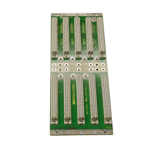
| Form Factor | 6U J1/J2; designed for VME and VME64x systems |
|---|---|
| Free Slots | Available configurations: 2, 3, 4, 5, 6, 7, 8, 9, 10, 12, 14, 16, 19, 20, and 21 slots |
| Backplanes | Slot pitch: 4 HP (20.32 mm); active or passive termination on/in the backplane; daisy chaining/bus grant electronically automatic using an OR gate, manual using jumpers or wire-wrap on request, and mechanically automatic using switching connectors |
| Power & Efficiency | Power consumption with both ends terminated: active < 0.2 A, passive < 1.3 A; permissible current loads: terminal bar 200 A, combined double-spade/screw connection 25 A, and Faston connector 10 A; current load per slot: +5 V 9.0 A, +12 V 1.5 A, −12 V 1.5 A, and +5 V standby 1.5 A |
| Connector | 96-pin, 2 mm press-fit connectors, quality grade 2; power-supply connection via M4 screw-type connection or Faston 6.3 × 0.8 mm; chassis-ground connection via combined M6 screw and Faston 6.3 × 0.8 mm |
VME64-6U-162-Datasheets
481.24 KB | 21. September 2026
General Safety Instruction
582.34 KB | 6. Juli 2026

Dieser Bereich ist exklusiv für Kontron-Kunden. Nach der Registrierung erhalten Sie Zugang zu BIOS-Images, Product Change Notifications (PCNs), 3D-Modellen für CAD und Software-Entwicklungstools.