VME64-6U-162-Datasheets
481.24 KB | September 21, 2026


The Kontron Hartmann Wiener VME/VME64x 6U Series 162 provides flexible backplane configurations for VME and VME64x systems. The series supports configurations from 2 to 21 slots with a consistent slot pitch of 4 HP or 20.32 mm and is designed for J1/J2 applications.
Three daisy-chain and bus-grant methods are supported: electronically automatic operation using an OR gate, manual configuration using jumpers or wire-wrap on request, and mechanically automatic operation using switching connectors. Depending on the selected variant, the backplane is available with active or passive termination.
The RF-optimized PCB design uses FR-4 material and complies with the ANSI/VITA 1.1-1997 base specification. A continuous chassis-ground surface is provided in the backplane mounting area. Rack and system ground are RF-coupled at each slot using a 10 nF, 200 V capacitor.
With a current capacity of up to 9.0 A per slot on the +5 V rail and up to 200 A through the terminal bar, the Series 162 is suitable for high-performance VME and VME64x systems. Typical application areas include military systems, transportation, medical imaging, telecommunications, industrial controls, and aerospace.
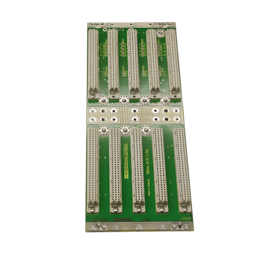
| Form Factor | 6U J1/J2; designed for VME and VME64x systems |
|---|---|
| Free Slots | Available configurations: 2, 3, 4, 5, 6, 7, 8, 9, 10, 12, 14, 16, 19, 20, and 21 slots |
| Backplanes | Slot pitch: 4 HP (20.32 mm); active or passive termination on/in the backplane; daisy chaining/bus grant electronically automatic using an OR gate, manual using jumpers or wire-wrap on request, and mechanically automatic using switching connectors |
| Power & Efficiency | Power consumption with both ends terminated: active < 0.2 A, passive < 1.3 A; permissible current loads: terminal bar 200 A, combined double-spade/screw connection 25 A, and Faston connector 10 A; current load per slot: +5 V 9.0 A, +12 V 1.5 A, −12 V 1.5 A, and +5 V standby 1.5 A |
| Connector | 96-pin, 2 mm press-fit connectors, quality grade 2; power-supply connection via M4 screw-type connection or Faston 6.3 × 0.8 mm; chassis-ground connection via combined M6 screw and Faston 6.3 × 0.8 mm |

This section is exclusively for Kontron customers. After registration, you will gain access to BIOS images, Product Change Notifications (PCNs), 3D models for CAD, and software development tools.