Smart Gate SG-21

Contactless card and QR code validator for railway and metro stations

  • More than 20 users per minute
  • 2 x Scanning performance on virtually any 1D & 2D barcode device
  • 26 x Photoelectric sensor (emitter/receiver)
  • 2 x information TFT screen 24"
  • RGB LED guiding lighting system
Product Thumbnail
Product Thumbnail
Product Thumbnail

Product Information

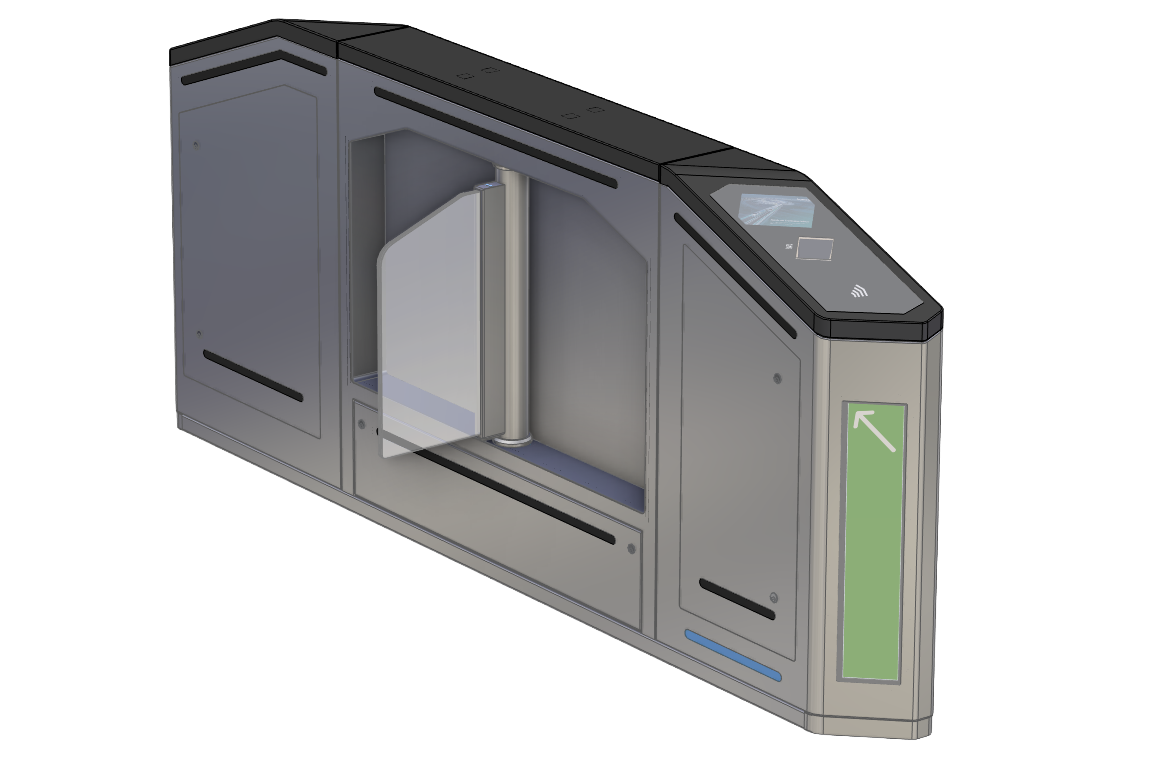
The Smart Gate SG-21 (model 21-21) is designed for validating transport tickets, whether contactless or QR code-based. It allows or denies users passage and simultaneously informs the user about the device's status (enabled or disabled), the validation result, passage authorization, and other information external to the device itself.

A complete gate consists of two units, two chassis, with sliding gates, one on each side of the passageway. These two units are also part of the access control system for adjacent passageways. Therefore, the equipment for controlling a gate is distributed between the two units that make up the passageway. This means that testing is performed on the gates themselves, not the units. However, one of the two units houses the gate control PC; therefore, this is called the master unit (usually located on the right side of the passageway as viewed from the station entrance), and the other unit is called the slave unit (generally the one on the left). The main functions of access control barriers are:

  • To allow passage to passengers with valid tickets and/or transport cards, and to block passage to passengers without tickets.
  • To inform passengers, through permitted/prohibited signage, about the equipment they can use at each station and at any given time, and to notify them via a TFT display of the actions they must take and the results thereof.
  • To allow safe passage for passengers with valid tickets using photoelectric cells that track their movement and prevent accidents with the flaps.
  • To indicate to passengers, using pictograms, that a barrier is inoperative when it has been activated in the opposite direction.

To perform these functions, the equipment includes the following components, integrated into the two units that make up the Access Control Unit:

  • The unit's control electronics (unit CPU mounting plate)
  • Opening and closing mechanism (right and left sides)
  • Contactless entry and exit validators
  • Contactless EMV bank card reader (entry)
  • Barcode readers (entry and exit)
  • User displays (entry and exit)
  • Front information displays (entry and exit)
  • Photocells connected to the CAN bus (26 units)
  • LED lighting system
  • Entry and exit cameras
Product Image 1

Technical data

Dimensions (H x W x D)1000 x 200 x 2500 mm
Weight235Kg
InterfaceEthernet
ConnectorShielded RJ45 connectors (external interface) AC input power terminals Internal distribution terminal blocks
Input Voltage230 VAC ±10 % (50 Hz)

Downloads

Manuals

PDF

General Safety Instruction

628.88 KB | March 26, 2026

Service

PDF

Kontron Services Brochure

8.9 MB | March 26, 2026

Enhanced safety detection

High passenger throughput

Future‑ready payment support

Entry & exit cameras

Front information displays

Customer Portal

This section is exclusively for Kontron customers. After registration, you will gain access to BIOS images, Product Change Notifications (PCNs), 3D models for CAD, and software development tools.

Log in to Customer Portal
Kontron logo